- This topic is empty.
-
AuthorPosts
-
27/10/2026 at 18:13 #9456
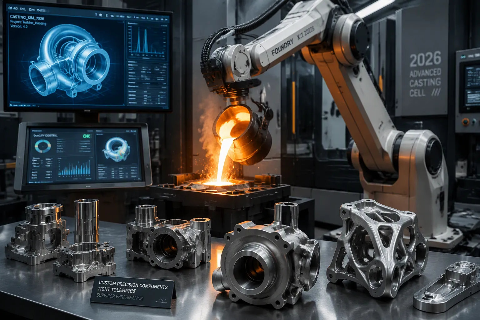
Image Source: https://www.xuxiangtaimetal.com Precision casting holds tight, repeatable tolerances through three elements: a dimensionally stable wax pattern, a rigid ceramic shell, and controlled melt and pour parameters. These elements let manufacturers produce custom geometries near-net shape. Typical as-cast linear tolerances fall in the ±0.1–0.5 mm range, depending on size and alloy. Machining brings critical features to tighter limits. Precision depends on feature geometry, alloy, and process control—not one number applied to the whole drawing. Write a professional tolerance strategy feature by feature.
Key Takeaways
- Control the wax pattern, ceramic shell, and melt pour to hold tight tolerances.
- Cast complex shapes near-net and machine only critical surfaces to save cost and time.
- Assign tolerances by feature and write a clear inspection plan to avoid extra cost.
How Precision Casting Controls Accuracy
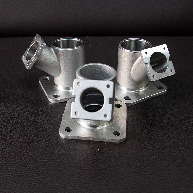
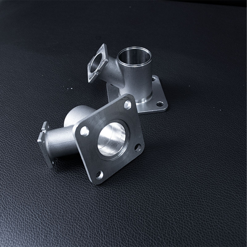
Accuracy in precision casting does not come from a single step. It emerges from a chain of controlled stages. Each stage adds or removes error. The wax pattern sets the starting geometry. The ceramic shell holds that geometry against the pressure of solidifying metal. The melt and pour parameters decide how the metal fills and shrinks. Near-net shape design then removes entire machining operations that would otherwise stack tolerances on top of each other. A manufacturer who understands this chain can assign tolerances with confidence. A manufacturer who ignores it will chase dimensional problems from one process step to the next.
Pattern and Tooling Dimensional Stability
The wax pattern is the first physical copy of the part. Any error in the pattern passes directly into the ceramic cavity and then into the final casting. Wax pattern distortion is a persistent quality challenge in investment casting. It affects dimensional accuracy, surface finish, and casting yield. The root cause is the thermal and mechanical sensitivity of wax. Temperature fluctuations during injection, cooling, and handling all move the pattern away from its intended shape.
Even minor dimensional deviations in wax patterns translate directly into defects in final cast components. These defects raise scrap rates, require extensive post-casting machining, and risk component failure in critical applications. In demanding sectors such as aerospace, medical devices, and precision machinery, distortion levels exceeding 0.1–0.2 mm can render components unusable. Distortion control is therefore essential for meeting tight tolerances.
Distortion arises from thermal contraction, residual stresses, and material flow during injection molding. Non-uniform shrinkage is a common cause. Thin walls cool faster than thick sections. This difference induces warping, twisting, and dimensional change. Premature surface solidification traps internal stresses. Those stresses release later during handling or shell building and move the part again.
- Dimensional compensation adjusts pattern dimensions for known shrinkage and thermal contraction using computational and empirical data.
- Post-processing correction applies controlled heating or mechanical correction to minor distortions.
- Precision machining of the die itself holds tolerances below 0.02 mm.
- Injection parameters—temperature, pressure, holding time, die temperature, and cooling rate—are optimized and locked.
Controlling wax pattern distortion is a fundamental enabler for meeting stringent quality requirements, reducing lead times, and maintaining cost competitiveness. The tooling that produces the wax pattern deserves the same attention. A die machined to tight tolerances and maintained on a fixed schedule gives the pattern a stable starting point. Pattern stability is the first link in the accuracy chain, and it is the cheapest place to fix an error.
Shell Rigidity and Dimensional Repeatability
The ceramic shell acts as the mold cavity and as a mechanical constraint on the solidifying metal. Its rigidity decides how much the casting can shrink freely and how much the shell holds back. Precision experiments identify an optimal high-temperature flexural strength of 3–4 MPa for the ceramic shell. This window is narrow for a reason.
- Too low rigidity: the shell shrinks together with the solidifying alloy and provides no effective constraint. The actual shrinkage rate far exceeds the design value, and castings come out undersized.
- Too high rigidity: shrinkage is fully locked, and large internal shrinkage stresses build up. These stresses cause thermal cracking and structural distortion.
- Balanced constraint: within the 3–4 MPa window, the shell provides moderate flexible constraint. This reduces free solidification shrinkage by about 30%, controlling dimensional deviation while avoiding rigid-constraint cracking.
Modern shell systems reach this balance through material design. Silane-coupled chopped carbon fibers form a cross-linked network in the silica sol matrix. This network bridges micro-cracks and disperses high-temperature stress. It cuts the ceramic’s high-temperature creep rate by an order of magnitude and suppresses uneven local deformation. During firing, the fibers oxidize away and leave uniformly distributed closed micro-pores. These pores give the shell trace flexible deformation space. The result prevents thermal cracks from excessive rigidity while avoiding insufficient constraint. High-temperature strength and flexibility stay in balance, and long-term dimensional stability follows.
During solidification, the shell and casting interact mechanically. Local stiffness variation matters. If shell stiffness varies across the part, some regions over-restrain shrinkage while others allow unrestricted contraction. This inconsistent restraint creates localized dimensional shifts. Those shifts enlarge existing deviations. Final dimensions therefore result from multiple coupled amplification mechanisms acting together, not from a single shrinkage factor.
Shell material choice changes hot behavior. Alumina offers higher hot strength at 900°C, but its deformation rate at 1300°C is nearly three times greater than calcined bauxite, and it softens at 1250–1300°C. Low hot creep resistance lets the shell yield under solidification stress and allows casting distortion. Calcined bauxite shows marginally lower mid-range strength but lower thermal expansion and superior resistance to high-temperature deformation. It gives better dimensional fidelity.
Shell material Hot strength at 900°C Deformation rate at 1300°C Effect on dimensional control Alumina Higher Nearly 3× greater than calcined bauxite (softens at 1250–1300°C) Low hot creep resistance lets the shell yield under solidification stress, allowing casting distortion Calcined bauxite Marginally lower mid-range strength Lower Lower thermal expansion and superior resistance to high-temperature deformation, giving better dimensional fidelity Layer composition and thickness complete the picture. A zircon face coat provides low CTE and good thermal stability at the metal interface. A mullite transition layer bridges the CTE gap between zircon and alumina. A high-alumina bauxite backup layer supplies strength at reasonable cost. A 1–2% nano-yttria (Y2O3) stabilizer improves thermal fatigue life by 15–20% through toughening and crack deflection.
Aspect Specification Purpose / Effect Face coat material Zircon Low CTE and good thermal stability Transition layer material Mullite CTE between zircon and alumina Backup layer material High-alumina bauxite Strength and cost effectiveness Stabilizer additive 1–2% nano-yttria (Y2O3) Improves thermal fatigue life by 15–20% via toughening and crack deflection Shell thickness (conventional) 8–10 mm Baseline Shell thickness (carbon fiber reinforced) 5–7 mm Reduced thickness with improved heat dissipation Shell thickness (integrated control) 5 mm (from 8 mm) 37.5% thinner shell Integrated shell control delivers measurable results. Thermal stress in the shell drops by more than 35%. Casting yield rises from 65% to 92%. Dimensional accuracy improves from worse than CT7 to CT7 or better. Shell thickness falls from 8 mm to 5 mm. A thinner, better-controlled shell also dissipates heat more evenly, which supports uniform solidification.
Melt, Pour, and Solidification Control
Metal temperature and shell temperature jointly govern how the casting fills and solidifies. Both must stay inside a defined window. Outside that window, dimensional accuracy suffers in predictable ways.
Elevated melt superheat improves fluidity. It also increases gas solubility and turbulence. When not properly controlled, these effects promote shrinkage porosity and reduce dimensional accuracy. Strict control of pouring temperature, alongside mold temperature and gating consistency, is a prerequisite for high-precision casting.
Temperature Condition Effect on Dimensional Accuracy Shell temperature too high Ceramic shell cracking causes shell inclusion, improper part geometry, inconsistent cooling, and rough surfaces Metal temperature too high Shell cracks and failures, gas porosity, shrinkage cavities, poor surface finish, and dimensional inaccuracy or failed parts Shell temperature too low Cold shuts and incomplete mold filling, thermal shock cracks, warping, distortion, and tears leading to dimensional failures Metal temperature too low Premature solidification causes incomplete pours, part inaccuracies, ceramic inclusion, and overall part failure Shrinkage allowance is alloy-specific. Each alloy family contracts by a different percentage as it cools from liquid to solid and then to room temperature. Tooling must compensate for the correct value.
Alloy Investment Casting Shrinkage (%) Aluminum Alloys 1.2 – 1.8 Magnesium Alloys 1.5 – 2.0 Zinc Alloys 1.0 – 1.5 Copper Alloys 1.2 – 1.8 Cast Iron 1.0 – 1.5 Steel 1.8 – 2.3 Solidification modeling turns these numbers into a predictive tool. Numerical analysis simulates solidification and predicts where shrinkage defects will form. Finite element modeling (FEM) analyzes temperature distribution and cooling rates. Computational fluid dynamics (CFD) models material flow during solidification. Pre-production simulation identifies potential defect locations and optimizes process parameters before any metal is poured.
Engineers then adjust the physical process to match the model. Optimized gating systems, riser placement, cooling channels, thermal management structures, and mold geometry engineered for directional solidification all feed the casting properly and compensate for volume reduction during cooling. Pouring temperature, cooling rate, pressure application, solidification time, and real-time monitoring keep cooling uniform and minimize internal voids and porosity. Alloy composition also plays a role. Grain refiners and modifying agents influence solidification behavior and help minimize volumetric contraction.
A typical simulation workflow follows a fixed sequence:
- Solve coupled heat and mass transfer in the solidifying casting using the finite element method (FEM).
- Build a mesh model of the computational domain comprising metal, ceramic shell, and thermal insulation.
- Use an automatic shell generator to create the ceramic shell and insulation mesh with specified thicknesses from the part’s 3D model.
- Run Euler flow, Fourier solidification, and Hooke stress solvers in a single run on multi-threaded CPUs.
- Review temperature and velocity fields, solidification dynamics, free-surface evolution, hot-spot and shrinkage-risk maps, and residual-stress fields.
- Apply the results to the part—for example, a turbine blade nickel superalloy investment casting—to predict shrinkage porosity, where hot spots form at blade-to-platform transition zones and the central region shows shrinkage-defect tendency.
This workflow converts process control from trial and error into a planned sequence. The foundry knows where shrinkage will occur before the first pour. Gating and riser design change on the screen, not on the shop floor.
Near-Net Shape Reduces Stacked Tolerances
Every machining operation adds a setup, a fixture, and a tolerance. Stack enough operations and the tolerances accumulate. Near-net shape casting removes that accumulation at the source. Precision casting holds tight dimensional tolerances typically in the ±0.05 mm to ±0.13 mm range with excellent surface finishes of 1.6–3.2 μm Ra. Compared with traditional sand casting, precision-cast parts can hold tolerance classes IT5–IT7 and often skip secondary machining entirely.
Feature Standalone Casting Casting + CNC Machining Tolerance Moderate Very Tight Consistency Good Excellent Surface Finish Rough Smooth Casting first produces a near-net-shape part. The initial piece is already very close to the final geometry. The CNC machine then performs minimal finishing work, removing small amounts of material to achieve tight tolerances and surface finishes. Fewer operations mean fewer fixtures, fewer datum transfers, and fewer chances for error to enter the part.
A 5-axis machine can finish a complex part in one single setup. This process avoids tolerance stack-up from multiple fixtures.
The practical effect is a shorter tolerance chain. A part machined from bar stock may pass through five or six operations, each with its own fixture and datum. A near-net casting may need one or two finishing operations on critical interfaces only. The casting carries the general geometry. Machining touches only the surfaces that demand tighter limits. This division of labor keeps cost down and accuracy up at the same time.
Cast or Machine: Feature-by-Feature Decisions
Image Source: https://www.xuxiangtaimetal.com A custom component rarely belongs entirely to the casting process or entirely to the machining process. The smartest manufacturing plan splits the drawing feature by feature. Complex geometry, curved surfaces, and ribs come from the mold at near-net shape. Threads, bearing seats, and sealing surfaces go to the CNC mill or lathe. This hybrid route captures the best economics of both processes. It also keeps the tolerance chain short and the inspection plan simple. The sections below walk through each decision category in turn.
Features Best Left As-Cast
The casting process earns its keep on geometry that would be slow and wasteful to cut from solid stock. Complex contours, curved surfaces, ribs, and non-critical exterior features all belong in the as-cast category. A machinist who starts from a billet must remove large volumes of material to reach these shapes. A casting arrives at that geometry in a single pour. The near-net shape leaves only a thin layer of stock for finishing.
Casting can minimize scrap by creating a part that is already near net shape, so only critical surfaces and threads need to be machined.
Exterior contours and ribs usually stay as-cast unless they control assembly fit. A rib that stiffens a housing does not need a machined face. A curved fairing on a pump body does not need a ground finish. These features serve structural or aesthetic purposes. Their as-cast tolerance is sufficient for the job.
Raised text, logos, and part numbers also belong in the mold. The pattern can carry these details with a minimum height of 0.020 in. Definition is best when the raised feature sits inside a recessed pad. This small design choice protects the lettering during shell building and handling.
As-cast features carry wider dimensional tolerances than machined surfaces. Larger dimensions and non-critical surfaces show more variation from wax pattern shrinkage, ceramic shell behavior, and metal solidification. The table below gives the standard recommendations for as-cast feature tolerances.
Feature Category Recommended Tolerance Linear Dimensions (standard) ±0.005 in per inch typical; add ±0.010 in for heavier sections or unsupported spans Wall Thickness Small castings: 0.030–0.060 in; medium & large castings: 0.080–0.100 in Flatness 0.005 in per inch of length Straightness Add 0.010 in for thicker sections or long, unsupported features Raised Features (text, logos, numbers) Minimum height 0.020 in; best definition when raised inside a recessed pad These numbers give the design engineer a realistic baseline. A drawing that assigns ±0.05 mm to every surface ignores how the process actually behaves. A drawing that assigns the values above to non-critical surfaces frees the foundry to deliver a sound part at a fair price.
Features That Should Be Machined
Some features demand a level of precision that no casting process can deliver directly from the mold. Threads are the clearest example. Wax-pattern investment casting cannot hold thread geometry to specification. The pattern material is too soft and the solidification shrinkage too variable. Threads are therefore drilled and tapped after the casting cools.
Tight-tolerance bores, mating surfaces, bearing seats, sealing surfaces, and assembly interfaces all fall into the same category. These features carry functional requirements that exceed as-cast capability. As-cast investment castings typically hold ±0.25 mm to ±0.76 mm. Precision CNC machining brings critical functional features to ±0.025 mm or tighter for aerospace, valve, and precision equipment applications.
Feature requiring post-cast machining Why machining is needed Threads Wax-pattern investment casting cannot hold thread geometry to spec Tight-tolerance bores As-cast process cannot achieve the required bore tolerances Mating surfaces Cannot be held to specification directly from casting Bearing seats Critical functional features needing ±0.025 mm or tighter after CNC machining Sealing surfaces Critical functional features requiring tight tolerances post-machining Assembly interfaces Critical functional features requiring tight tolerances post-machining Rotating and wear-exposed cylindrical parts deserve special mention. Grinding removes minimal stock to achieve final tolerance and surface finish. This step is especially critical where roundness and finish quality directly affect service life. A bearing journal that runs out of round will fail early no matter how good the rest of the part is.
The practical rule is simple. Cast the complex geometry, then machine only the functional surfaces. This hybrid route minimizes cost and lead time. It also concentrates inspection effort where it matters most.
Datum Strategy for Mixed Cast-and-Machine Parts
A mixed cast-and-machine part needs a datum plan that connects the casting to the machining setup. Without that plan, the machinist guesses where the part sits in space. The result is uneven wall thickness, missed features, and scrap.
The first principle is to choose datum areas that span the largest possible area. Wide spacing minimizes alignment error. Spread the targets out so the part is fixtured with greater stability. A datum cluster squeezed into one corner gives the setup less leverage against cutting forces.
The second principle is to avoid common defect zones. Datum areas and targets should stay away from parting lines, sprues, and other locations where casting defects tend to appear. A datum placed on a sprue stub will shift when the stub is removed. A datum placed near a parting line will inherit the mismatch between mold halves.
The third principle is proper constraint. The fixture should constrain exactly all six degrees of freedom without over- or under-constraining the part. A 3-2-1 target arrangement does this well: three points on the primary datum, two on the secondary, one on the tertiary.
- Choose datum areas and targets that span the largest possible area to minimize alignment error, and spread targets out so the part is fixtured with greater stability.
- Avoid placing datum areas or targets near parting lines, sprues, or other common casting defect zones.
- Constrain exactly all six degrees of freedom (for example, a 3-2-1 target arrangement: 3 points primary, 2 secondary, 1 tertiary) without over- or under-constraining the part.
- Keep datums out of functional areas; they should instead help balance the part so consistent, even wall thickness is maintained during machining.
- Ensure the print defines each datum’s location relative to the others with basic dimensions (a datum relationship table in all three cardinal directions), since missing relationships are a common measurement-error source.
- For legacy parts lacking casting datums, derive them from the previous supplier’s machining setups, or from a stable machining fixture used across all operations; the machining setups should always match the casting datum reference frame, and the chosen datums should be reviewed and documented with the end customer.
- A casting datum may serve as a final part datum if it functionally meets the design engineer’s intent.
The datum relationship table deserves emphasis. Missing relationships between datums are a common source of measurement error. The print should define each datum’s location relative to the others with basic dimensions in all three cardinal directions. A machinist who must infer these relationships will eventually infer them differently than the inspector.
Feature Decision Matrix: Tolerance, Finish, and Cost
The cast-or-machine decision is not a matter of preference. It is a calculation that weighs tolerance, finish, cost, volume, and lead time. A feature decision matrix makes that calculation visible and repeatable.
Several factors belong in the matrix. Production volume matters because higher volumes favor casting. Tooling costs are amortized across units, so the per-part price falls as volume rises. Timeline urgency matters because tight development schedules may favor machining despite higher per-unit costs. Design complexity matters because complex geometries may be more easily achieved through machining. Material requirements may dictate the manufacturing method. Weight, cost, timeline, and performance requirements should all be weighted in the matrix. Tooling investment differs sharply: casting requires substantial upfront tooling spend, while machining uses lower-cost fixtures and programs. Inspection and quality control strategy also differs. Machined parts suit conventional CMM inspection, while cast parts often need specialized inspection for complex geometries and defects. Design feature compatibility completes the list. Cast parts need draft angles and generous radii. Machined parts accommodate tighter tolerances and sharper features.
The cost picture changes with volume. The table below shows the break-even pattern for a typical industrial component.
Volume Range Machining Cost/Part Casting Cost/Part Break-Even Insight 1–10 parts $200–$1000 Not viable (tooling prohibitive) Machining only 10–100 parts $200–$1000 $150–$300 (amortized tooling) Depends on tooling complexity 100–1000 parts $200–$1000 $50–$150 Casting becomes cost-effective 1000+ parts $200–$1000 $10–$50 Casting yields significant savings Tooling investment $500–$5,000 (fixtures/programs) $25,000–$150,000 (molds) Volume determines ROI timeline The matrix also captures the material waste difference. Near-net-shape production leaves minimal material to remove, which significantly reduces wasted material and contributes to cost savings. Machining from a larger billet or block generates more waste. Tooling cost cuts the other way. Casting requires expensive molds, and that investment makes sense once the design is stable. Machining needs no molds, but it needs expensive cutting tools.
High-volume production generally favors casting. The incremental cost per part stays low once the mold is ready. Die casting is the cheapest option at volume, followed by investment casting and sand casting. Low-volume production favors machining. It is faster and more economical for low volumes and simple parts because no mold preparation is needed. Complex and intricate geometry favors casting, especially shapes with sharp internal corners that are difficult or expensive to machine. Machining cannot produce sharp internal corners and edges, but it excels at threads, precise round holes, and straight edges. Design changes favor machining because it is more flexible and adaptable to design modifications. Molds must be adjusted or replaced when the design changes, which adds cost. Tight tolerances and precise repeatability favor machining when the requirement is exceptionally demanding.
A well-built matrix turns these trade-offs into a clear recommendation for each feature. The design engineer can then defend the drawing with data rather than habit.
Design, Inspection, Cost, and RFQ Essentials
Design Factors That Complicate Tight Tolerances
Geometry drives tolerance capability. Long, slender sections, thin-wall areas, deep grooves, and asymmetric structures all increase dimensional deviation. Investment casting reaches roughly ±0.005 inches per inch, yet thin walls below 0.040 inches limit consistent mechanical properties. Stainless steel shrinks more and reacts sharply to thin walls and deep slots. Designers can improve stability by adding radii, reducing thin walls, and holding wall thickness consistent.
Design factor How it complicates tight tolerances Wall thickness and section transitions Abrupt changes cause uneven cooling, shrinkage, and distortion Component geometry and complexity Complex shapes and internal features disturb metal flow and solidification Draft angles, fillets, and radii Sharp corners create stress points that shift final dimensions Material and process selection Alloy shrinkage and process capability set the accuracy ceiling Over-tolerancing non-critical features Raises cost and scrap without functional gain Over-tolerancing is a common trap. A bracket that needs only hole location held tightly does not need ±0.0002 in on every surface. Relaxing non-critical callouts to realistic values keeps function intact and makes production faster and cheaper.
Specifying Inspection and Documentation
A clear inspection plan removes ambiguity at delivery. Buyers should name the verification method and the acceptance criteria for each critical dimension.
- Documentation: First Article Inspection records, AS9102 forms for aerospace work, and quality records for audits
- Dimensional measurement: CMMs at ±0.0001 to ±0.0005 in, optical systems, and hand tools
- Surface finish: profilometry, visual comparison, fluorescent penetrant, magnetic particle
- Material verification: hardness testing, metallurgical analysis, spectroscopy
- Nondestructive testing: ultrasonic, radiographic, eddy current
- In-process control: control charts, capability studies, Gage R&R
Chemical composition testing of every melt, recorded electronically, supports full traceability. Write a professional inspection clause that ties each requirement to a standard.
How Tolerance Choices Drive Cost and Lead Time
Tightening from DCTG 7–9 to DCTG 4–6 raises per-part cost by 20–40%. The increase comes from several sources.
- Inspection overhead adds roughly 2–4 weeks per order for CMM programming and first-article approval.
- Scrap rates rise as the process nears its capability limit.
- Secondary operations grow because as-cast parts cannot hold sub-0.1 mm reliably.
- Fewer than 40% of qualified foundries accept sub-CT5 requirements, which shrinks the vendor pool.
For features needing sub-0.1 mm, plan a machining allowance of 1.0 mm or more. Write a professional tolerance callout only where function demands it.
Write a Professional RFQ Data Package and Design-for-Casting Review
A complete RFQ package lets suppliers quote against a defined process. Write a professional package that covers certification scope, material grade with its standard, surface treatment, tolerance class with inspection method, and quantity with lead time.
Inspection element Purpose in the RFQ Direct-reading spectrometer Verifies alloy chemistry before production X-ray or industrial CT Detects internal shrinkage and porosity CMM Validates dimensional consistency Mechanical property testing Confirms strength and hardness Material traceability and MTC reports Ties each batch to furnace and inspection records Buyers should also state part size, geometry, CT grade, Ra target, and volume. Write a professional design-for-casting review before quoting to lock in precision, cost, and lead time.
Precision casting meets custom component requirements when engineers assign tolerances by feature and process capability. The decision path is clear: cast near-net shape, machine critical interfaces, specify inspection clearly, and share a complete RFQ package. Write a professional design-for-casting review before quoting. That review remains the most reliable way to lock in precision, cost, and lead time in 2026.
FAQ
What tolerance should a buyer assign to an as-cast surface?
Buyers should assign as-cast tolerances by feature and process capability. Typical linear values fall in the ±0.1–0.5 mm range. Critical interfaces then receive machining to tighter limits.
When does machining beat casting for a custom component?
Machining fits low volumes, simple shapes, and urgent schedules. Casting wins at higher volumes and complex geometry. Most custom parts combine both routes feature by feature.
What belongs in an RFQ package for a precision casting project?
A complete package includes 3D models, 2D drawings with datum callouts, alloy grade, tolerance class, inspection method, surface finish, quantity, and lead time. A design-for-casting review comes first.
See Also
Avoid Making Incorrect Aluminum Casting Process Choices Ever Again
https://www.xuxiangtaimetal.com
Qingdao Xuxiangtai Machinery -
AuthorPosts

- You must be logged in to reply to this topic.